Magnetic Induction
Tasks/Objectives
- Predict and test the current direction through a coil of copper wire when a magnet is dropped through it
- Determine the relationship between magnetic field flux and induced current
Resources
- Air core solenoid
- Base plate with LEDs
- Giant Neodymium Magnet
- North marked with red sticker
- Wires
- Plastic Tube
- Stand with clamps
- Voltage sensor and computer interface
- setup file faradayslaw.ds
Background
If the magnetic field through a wire loop changes, it induces a current in the wire loop. The direction of the current is given by Lenz’s Law, which states that the current direction is such that it creates a magnetic field opposing the direction of change of the external field.
Faraday’s Law states that the electromotive force in a wire loop is equal to the time rate of change of the magnetic flux through the loop, or
V=-N\frac{d\Phi}{dt} = -N\frac{\Delta(BA)}{\Delta t}Equipment Notes
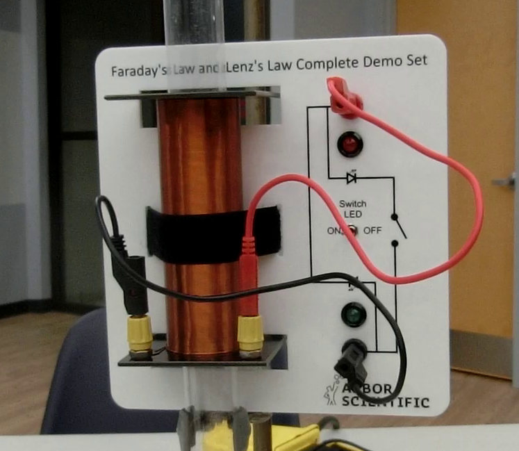
- Looking at the plugs on the base of the solenoid, it can be determined the direction in which the wires from each plug are wound around the solenoid (i.e. clockwise vs. counter-clockwise).
- The base plate for mounting the solenoid also has two LEDs that can be connected to the coil with wires. Current can only flow through each LED in the direction indicated by the arrow symbol. The switch disables the red LED, so only the green can light up.
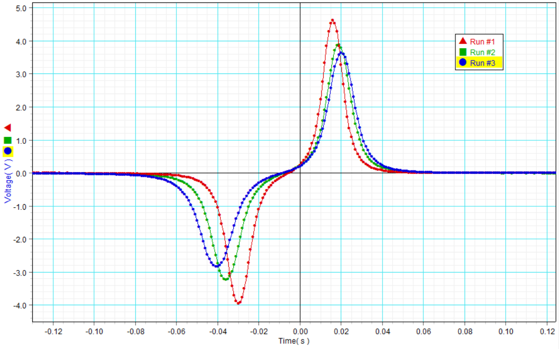
- The included DataStudio experiment file is set up so that when data collection begins, data is not saved until a voltage spike is detected. Then, only a one-second window of data around the voltage spike is saved. This allows the induced emf created by the falling magnet to be sampled at high resolution, without also capturing a lot of extra useless data.