Capacitors
In this lab you will study how current and voltage changes in simple electrical circuits and inside standard components.
Objectives
- Measure the capacitance of a capacitor using only a voltmeter
- Study how capacitors behave when connected in series and parallel
Resources
- 9V battery
- resistor
- two standard capacitors (pF-nF range)
- a large-value capacitor (100μF or greater)
- a large-value resistor (at least 10K ohms)
- hook-up wires with clips
- multimeter
- capacitance meter
- a stopwatch or stopwatch app (i.e. online-stopwatch.com)
Background
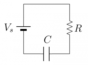
 A capacitor stores an amount of charge proportional to the voltage across it. However, because charge takes time to move through a circuit depending on the amount of resistance in the wires or components, the charge and voltage on a capacitor are not constant. If the circuit shown is left connected long enough for the capacitor to charge to the supply voltage V_s, and then the supply voltage is removed and the circuit reconnected, the capacitor will discharge according to \frac{Q}{C}=V=V_s e^{-t/RC}
Guideposts/Hints
- Make sure you understand how to measure current and voltage with a multimeter.
- You can see from the above equation that the capacitor will be a little over 60% charged after a time roughly equal to the resistance multiplied by the capacitance, so you may want to choose an appropriate resistance so that you have to to make multiple measurements.
- Some types of capacitors have a dielectric that polarizes better when the voltage travels in one direction versus the other. This is usually indicated by a negative sign, stripe, or arrow pointing to the terminal that should be connected to the lower voltage or ground.