Semiconductor Components
Objectives
- Study the voltage vs. current behavior of a diode
- Determine the voltage drop across a diode operating in forward-biased mode.
- See how a transistor functions as a current “valve”
Resources
- Prototyping station with variable (15V) power supply
- Diode
- Light-emitting diode (LED)
- Transistor (2N3904)
- Resistors (1K Ohm, 10k Ohm)
- Wires
- Multimeter
Background
Diodes and transistors are semiconductor components that use the properties of p-n junctions, which are just two different metals layered on top of each other, for their function. One of the metals has an excess of electrons (n-type), and the other has a corresponding lack of electrons (p-type). The way current travels across these junctions is fundamentally quantum mechanical in nature.
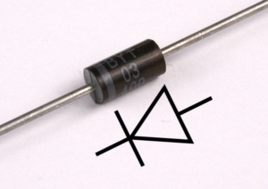
A diode is a component ideally conducts current in one direction only, and blocks it in the other. Real diodes don’t perfectly conduct in the forward direction. The most common types of diode have a voltage drop of roughly 0.7 Volts. Most diodes have a stripe to indicate the direction of allowed current flow. The diode symbol is an arrow with a stripe showing the current direction.
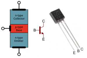
A transistor is a sandwich of two p-n junctions, and has a lead/connection to each layer. Thus, a transistor has three legs, unlike resistors, capacitors, etc. The three legs are called the emitter, base, and collector. The base acts like a switch – when there is enough current at the base, current can flow between the collector and emitter. If there is no current at the base, collector-emitter current is blocked. A transistor can also act like an amplifier – a small current at the base of the transistor can allow a larger proportional current into the collector.
Method
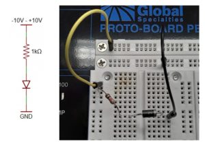
Construct the circuit schematic below on the prototyping station as shown in the image. Apply voltages over the range -10 Volts to 10 Volts to the circuit. For each applied voltage, measure the voltage drop across the diode and across the resistor. Use the voltage across the resistor together with Ohm’s Law V=IR to determine the current in the circuit. Plot the diode’s current vs. voltage.
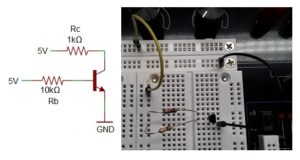
Construct the transistor circuit below on the prototyping station. Measure the voltage across the collector resistor R_c and base resistor R_b and calculate the current into the collector and base. Disconnect one leg of the base resistor and determine the currents again.
Analysis Questions
- Does your current vs. voltage plot for the diode show that it conducts current in only one direction? What is the voltage drop across the diode in the forward-biased mode?
- Replace the diode with an LED. Does it also conduct current in only one direction? Explain how you know.
- What are the currents into the base and collector of the transistor when both resistors are connected? Is the transistor amplifying the current? Explain.
- What is the current into the collector of the transistor when there is no current at the base?


