Polarization of EM Waves
Tasks/Objectives
- Plot the intensity of linearly polarized light passing through a polarizing filter vs. the relative angle between the axis of the polarizer.
- Use a third filter between two perpendicularly-oriented polarizing filters to recover some of the blocked light.
Resources
- Light source
- Optics rail
- Polarizing filters
- Light sensor
- DataStudio software and ScienceWorkshop interface
- lightsensor.ds DataStudio setup file
Background
The polarization of a light wave is the direction in which its electric field oscillates. A light wave can be thought of as a traveling wave in the electric and magnetic field, both of which are oscillating perpendicular to each other and perpendicular to the direction the light wave is traveling. Many light sources produce unpolarized light, which is a combination of many waves with different polarizations in roughly equal proportion. Many lasers produce light that is partially polarized, meaning many polarizations are present but there are some that exist in a higher fraction. A polarizing filter is some sort of material that preferentially allows through light of only certain polarizations. The reduction in intensity I_0 of a light wave that passes through a polarizing filter is given by \frac{I}{I_0}=\cos^2\phi
where \phi is the angle between the polarization direction of the light wave and the polarization axis of the filter.
Setup
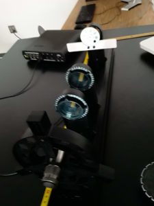
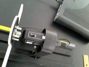
Set up the flashlight, polarizers, and light source on the optical bench as shown in the image above. The first polarizer’s function is to produce linearly polarized light from the randomly polarized light source. The aperture mask on the light sensor should be rotated to the diffuser (“filled circle”) position as shown.
When taking data, the light source may be too weak to trigger the sensor, or so bright that the sensor only reads maximum. Adjust the gain setting on the sensor as shown to compensate.
Analysis Questions
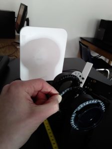
- With two polarizers between the laser and sensor as shown, rotate one polarizer through 0-360 degrees and plot the intensity vs. the relative angle between the polarizers’ axes. Compare to the result predicted above.
- If the two polarizing filters are oriented at 90 degrees to each other, all of the light should be blocked as shown by the formula above. However, if a third polarizer is inserted between the two, some of the light can be recovered. Test this yourself, show mathematically how this is possible and calculate the expected intensity.

