AC Circuits
Tasks/Objectives
- Use a square wave as the voltage source for an RC circuit.
- Study the charge/discharge rate of the RC circuit using an oscilloscope and determine its time constant.
- Measure the response of the RC circuit over a range of frequencies and discover its cutoff frequency.
Resources
- Oscilloscope
- AC (function) generator
- Resistor (~10 kΩ)
- Capacitor (~100 nF)
- Wires, alligator clips
Background
An RC circuit is simply a resistor and a capacitor connected in series. While the voltage across a resistor at any moment is always equal to its resistance multiplied by the current, the voltage across the capacitor is time-dependent. Assuming the capacitor is initially uncharged when constant voltage V_0 is supplied, the voltage across the capacitor at time t can be shown to be V(t)=V_0 (1-e^{-t/RC})
The value \tau=RC is called the time constant of the RC circuit, and gives rough sense of how quickly the capacitor charges. When t=\tau, then V=V_0 (1-e^{-1}) \approx 63\% V_0.
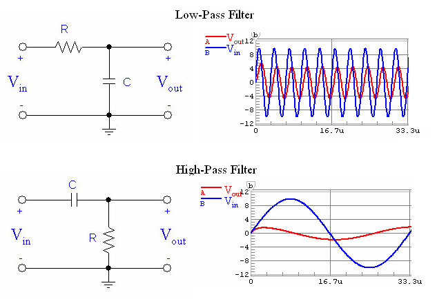
If the voltage provided to an RC circuit varies quickly, the capacitor will begin discharging before it has a chance to fully charge, and its voltage will wiggle around zero by a small fraction of V_0 Thus, the capacitor in an RC circuit acts to filter out high frequency signals. The voltage across the resistor, however, will swing by a large amount since most of the voltage is dropping there. If the input voltage varies slowly, the capacitor will be able to fully charge before the current switches direction and the voltage across the resistor will hover around zero, making the resistor a low-pass filter.
The cutoff frequency of an RC circuit is the frequency at which the average power output is half the input, meaning that the voltage (peak-to-peak or RMS) is reduced by a factor of \tfrac{1}{\sqrt{2}}. Mathematically, the cutoff frequency of an RC circuit is f_c=\frac{1}{2\pi RC}
Guideposts/Hints
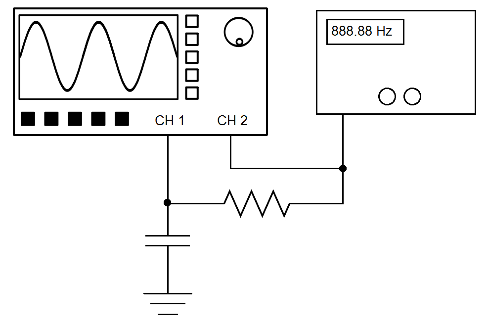
- In the simplest sense, an oscilloscope provides a graph of the voltage vs. time of whatever electrical signal you send into it. To get a feel for how the oscilloscopes work, try connecting the function generator directly into channel 1 of the oscilloscope. Press the “Autoset” button once to get some good initial settings, then play around with the knobs on the oscilloscope and generator to see what effects they have.
- The oscilloscope’s “Measure” button will allow you to measure quantities related to the signals coming in to the oscilloscope, such as peak-to-peak voltage, rms voltage, and frequency.
- The “Cursor” button allows you to place vertical or horizontal markers to directly measure the voltage or time off the screen.