HOW TO – Current Balance Setup
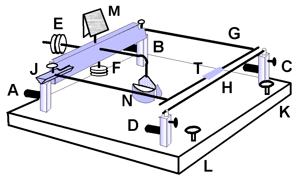
This is a brief description of the components of the current balance apparatus, as well as instructions for its use. The figure below shows the different components of the apparatus.
- A, B: Connections for power to upper tilting wire
- C, D: Connections for power to lower wire
- E, F: Adjustable weights for balancing tilting wire
- G: tilting, U-shaped wire
- H: lower straight wire
- J: balance points for tilting wire
- K,L: adjustment posts for leveling apparatus
- M: mirror for detecting small changes in tilt angle
- N: magnetic brake to dampen oscillations of tilting arm
- T: tray for adding mass to upper tilting wire
Setup Instructions
- Adjust upper arm of apparatus so that middle section of tilting wire (G) is directly above and parallel to lower wire (H).
- Connect wires from A and D to positive and ground (respectively) of step-down transformer.
- Connect B to C using hook-up wire.
- Aim laser beam at mirror (M) so that reflected beam falls on a wall or flat surface and small deviations in tilt of U-shaped wire can be detected.
- Plug step-down transformer into output of variable autotransformer (variac). Turn on variac and adjust to increase current in wires G, H.
